
EBSD Explained
Techniques
Applications
Hints and Tips
Technology
OXFORD INSTRUMENTS EBSD PRODUCTS
CMOS Detector RangeAZtecHKL Acquisition SoftwareAZtecCrystal Processing Software
Electron backscatter diffraction (EBSD) only works for crystalline (or quai-crystalline) materials. There is no electron diffraction for many sample types, including plastics, glass and many organic materials. In order to understand the principles of electron diffraction, as well as for the display and interpretation of EBSD results, it is necessary to have a basic understanding of the key principles of crystallography.
This page covers 3 main topics, accessible in the individual tabs below. “Crystals and Lattices” covers the basics of how the repeated arrangement of atoms can be used to define crystalline structures, “Crystal Symmetry” covers the different terminology used to define the symmetry of crystalline materials and “Directions, Planes and Zone Axes” introduces the ways in which we can represent these geometrical concepts.
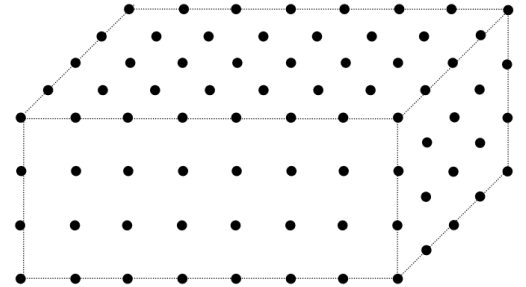
Crystalline material consists of a regular repetition of a group of atoms in three dimensional space. A crystal lattice is an infinitely repeating array of points (i.e. the groups of atoms) in space.
A schematic representation of a crystal lattice
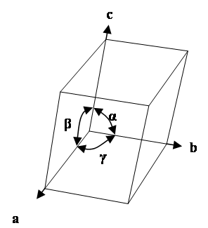
The unit cell is the basic repeating unit of the crystal lattice and is characterised by a parallelepiped with cell edge lengths a, b, c and inter axis angles α, β ,γ.
The unit cell of a crystal lattice
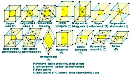
These unit cells can be classified as belonging to one of fourteen Bravais lattices (named after Auguste Bravais, 1850). Each Bravais lattice belongs to one of the seven crystal systems – these are introduced here.
The fourteen Bravais lattices
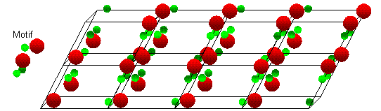
The motif is a group of atoms that is repeated at each lattice point.
An example crystal structure showing a repeated atomic motif at each lattice point.
Here, the key aspects of crystal symmetry are introduced, leading on from the concepts relating to Crystal and Lattices that were introduced on the previous tab. The crystal symmetry is an important concept for electron backscatter diffraction since a knowledge of a particular phase’s crystal symmetry will influence how we might display and interpret data collected using EBSD.
A crystallographic point group is a group of symmetry elements that operate on a 3-dimensional lattice to leave it unchanged. The symmetry elements are those of rotation (1, 2, 3, 4 and 6 fold axes) and rotation followed by inversion. For example, rotation about a 3-fold symmetry axis leaves space unchanged for every rotation of 120 degrees. The inversion symmetry elements are shown by the notation -1, -2, -3, -4, -6. -2 is equivalent to a mirror plane perpendicular to the rotation axis. The symmetry elements combine to form 32 point groups.
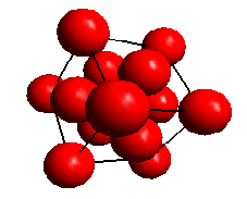
View along a <111> direction in a face centred cubic lattice showing the 3-fold symmetry. The lattice is unchanged for every rotation of 120 degrees about the <111> axis.
The point groups can be assigned to seven crystal systems, each with a symmetry element in common. A lattice with a unit cell exhibiting the required symmetry can then be assigned to each crystal system as shown in the following table. The terms a, b and c and α, β and γ refer to the unit cell dimensions (the lattice parameters and inter-axis angles, respectively). The unit cell is primitive because it has only one lattice point per cell (which is shared by the neighbouring cells).
| System | Symmetry Element | Conventional Unit Cell |
| Triclinic | One fold axis | a ≠ b ≠ c; α ≠ β ≠ γ |
| Monoclinic | Two fold axis (diad) | a ≠ b ≠ c; α = γ = 90°, β > 90° |
| Orthorhombic | Three mutually perpendicular diads | a ≠ b ≠ c; α = β = γ = 90° |
| Trigonal | Three fold axis (triad) | a = b = c; α = β = γ < 120°, ≠ 90° |
| Tetragonal | Four fold axis (tetrad) | a = b ≠ c; α = β = γ = 90° |
| Hexagonal | Six fold axis (hexad) | a = b ≠ c; α = β = 90°, γ = 120 ° |
| Cubic | Four triads (parallel to <111>) | a = b = c; α = β = γ = 90° |
Adapted from "Essentials of Crystallography" McKie D and McKie C, Blackwell Scientific Publications (1986)
Each of the lattices described above is based on a primitive unit cell. It is also possible to define lattices based on non-primitive unit cells which are consistent with the crystal symmetry in a system. These are the fourteen Bravais Lattices which are described in the following table.
| System | Lattice Symbol | Conventional Unit Cell | Number of lattice points |
| Triclinic | P | a ≠ b ≠ c; α ≠ β ≠ γ | 1 |
| Monoclinic | P | a ≠ b ≠ c; α = γ = 90°, β > 90° | 1 |
| Monoclinic | C | a ≠ b ≠ c; α = γ = 90°, β > 90° | 2 |
| Orthorhombic | P | a ≠ b ≠ c; α = β = γ = 90° | 1 |
| Orthorhombic | C | a ≠ b ≠ c; α = β = γ = 90° | 2 |
| Orthorhombic | I | a ≠ b ≠ c; α = β = γ = 90° | 2 |
| Orthorhombic | F | a ≠ b ≠ c; α = β = γ = 90° | 4 |
| Tetragonal | P | a = b ≠ c; α = β = γ = 90° | 1 |
| Tetragonal | I | a = b ≠ c; α = β = γ = 90° | 2 |
| Cubic | P | a = b = c; α = β = γ = 90° | 1 |
| Cubic | I | a = b = c; α = β = γ = 90° | 2 |
| Cubic | F | a = b = c; α = β = γ = 90° | 4 |
| Trigonal | R | a = b ≠ c; α = β = 90°, γ = 120° or a = b = c; α = β = γ < 120°, ≠ 90° | 3 |
| Hexagonal | P | a = b ≠ c; α = β = 90°, γ = 120° | 1 |
Adapted from "Essentials of Crystallography" McKie D and McKie C, Blackwell Scientific Publications (1986)
The fourteen Bravais lattices
Two other types of symmetry operation are those involving translation - the screw axes and glide plane. The screw axes combine a rotation with a translation and the glide plane a translation with reflection in a mirror. If these elements are combined with the point groups and the 14 fourteen Bravais lattices, there are 230 distinct arrangements; these are called “space groups”. Space groups are identified by a reference number, and the Hermann-Mauguin (HM) symbol and the Hall symbol which show the symmetry elements present.
If we consider a crystal structure in which there is an atom at x, y, z as well as one at -x, -y, -z, then the structure is said to have a centre of symmetry. Some of the 32 point groups do not have a centre of symmetry. Electron diffraction patterns have a centre of symmetry, so it is usually not possible to distinguish point groups with centres of symmetry from those without. This reduces the number of distinct point groups that can be distinguished with electron diffraction to the 11 Laue classes (or Laue groups).
In the table below, the Laue symbol is used to represent the symmetry elements characteristic to each Laue class.
| Crystal System | Laue | ID | Symmetry | Example Phases |
| Triclinic | -1 | 1 | Inversion centre as the only symmetry | Plagioclase Feldspar (e.g. NaAlSi₃O₈) |
| Monoclinic | 2/m | 2 | Two-fold rotation axis perpendicular to mirror plane | Clinopyroxenes (e.g. Ca(Mg,Fe)Si₂O₆); Monoclinic ZrO₂ |
| Orthorhombic | mmm | 3 | Three perpendicular mirror planes | Olivine ((Mg,Fe)₂SiO₄); Cementite (Fe₃C) |
| Tetragonal | 4/m | 4 | Four-fold axis with one perpendicular mirror plane | Leucite (KAlSi₂O₆) |
| Tetragonal | 4/mmm | 5 | Four-fold axis with three perpendicular mirror planes | Rutile (TiO₂); γ-TiAl |
| Trigonal | -3 | 6 | Three-fold rotation-inversion | Ilmenite (FeTiO₃) |
| Trigonal | -3m | 7 | Three-fold rotation-inversion with mirror plane | Quartz (SiO₂), α-alumina (Al₂O₃) |
| Hexagonal | 6/m | 8 | Six-fold axis with perpendicular mirror | Apatite (Ca₅(PO₄)₃(OH,F,Cl)) |
| Hexagonal | 6/mmm | 9 | Six-fold axis with three perpendicular mirror planes | Magnesium, α-Titanium |
| Cubic | m3 | 10 | Three-fold axis with one mirror | Pyrite (FeS₂) |
| Cubic | m3m | 11 | Three-fold axis with two mirror planes | Fe-BCC; Fe-FCC; Aluminium |
Table showing the 11 Laue classes, along with some typical example phases.
The content of the unit cell is described by an asymmetric unit (a primitive group of atoms) and the symmetry of the relevant space group. The symmetry operations of the space group act on the atoms in the asymmetric unit to generate the positions of all the atoms in the cell.
In some crystal structures, sites are not always occupied by the same atom throughout the crystal structure. The occupancy describes the percentage of times a particular site will be occupied by a particular chemical element.
Here we introduce the concepts relating to the labelling and representation of crystallographic planes and directions. This is usually done using the Miller or Miller-Bravais notations, which are described below.
These are essential for the effective recording of electron backscatter diffraction (EBSD) data in terms of textures and boundaries (rotation axes or boundary planes), as well as for a deeper understanding of the crystallographic principles of the EBSD technique.
Here we show how to describe a crystal direction using the Miller index notation. Consider a crystal lattice with unit cell edges a, b and c. A crystal direction [uvw] is parallel to the direction joining the origin of the crystal lattice with the point with coordinates (ua, vb, wc), as shown in the images below.
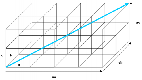
Illustration of the crystal direction [uvw]. The direction shown here is [422].
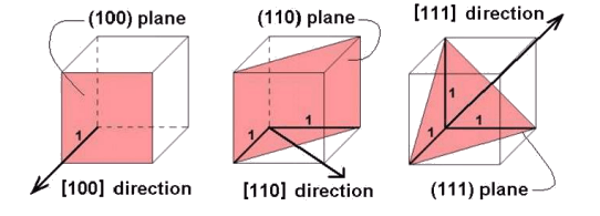
This shows how the [100], [110] and [111] directions are defined. The directions are perpendicular to the planes with same Miller indices only in materials with cubic symmetry.
Here we show how to describe a crystal plane using the Miller index notation. A plane with Miller indices (hkl) passes through the three points (a/h,0,0), (0, b/k,0) and (0,0, c/l) on the edges of the unit cell. The set of parallel lattice planes passes through all similar points in the lattice. The plane d-spacing is the perpendicular distance from the origin to the closest plane and also the perpendicular distance between successive planes. In materials with cubic symmetry the crystal direction [uvw] and the normal to the plane (uvw) are parallel.
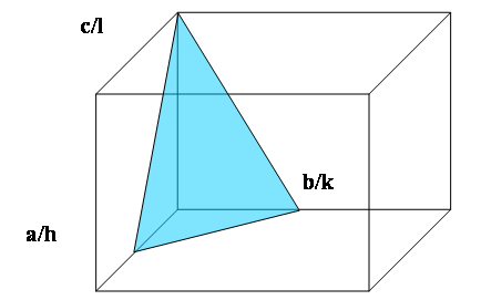
Crystal Planes 1: The plane with Miller indices (hkl) makes intercepts a/h, b/k and c/l on the edges of the unit cell. The plane shown here is (221) because the intercept in the a direction is ½a, in the b direction ½b and in c direction c.
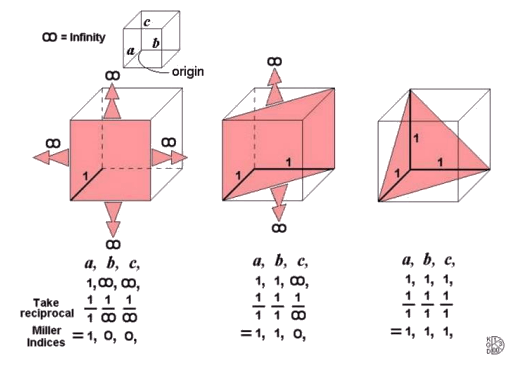
Crystal Planes 2: these schematic images show how the (100), (110) and (111) planes are defined.
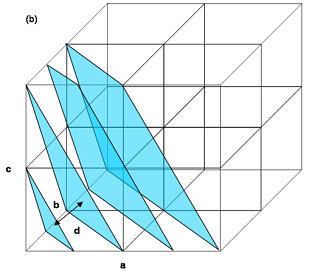
Crystal Planes 3: a set of parallel (221) planes intersecting the edges of the unit cells. The d-spacing, d for these planes is the perpendicular distance between successive planes or equivalently the perpendicular distance from the origin to the closest plane.
The common direction shared by two crystal planes when they intersect is called the zone axis. A zone axis [uvw] is always perpendicular to the plane normal (hkl) that comprises the zone, and this relation is stated in the zone law (also known as the Weiss zone law): uh + vk + wl = 0.
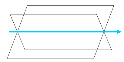
The zone axis is the common crystal direction shared by two planes.
The family of symmetrically related directions [uvw] is shown by the notation <uvw> and the family of symmetrically related planes (hkl) is shown by the notation {hkl}.
It is sometimes easier to define the unit cell of some crystals in a hexagonal reference frame (i.e. hexagonal and rhombohedral/trigonal crystal systems). In these cases there are, in fact, 4 axes in the unit cell – one along the long axis of the hexagonal cylinder (i.e. the 6-fold rotation axis) which is usually referred to as the “c” axis and 3 “a” axes in the basal plane, at 120° intervals.
For such systems the crystal directions and planes can be defined using a 4-digit notation, known as the Miller-Bravais notation. Calculating the Miller-Bravais indices for a plane is done in the same way as with the 3-digit Miller indices.
It is possible to use the Miller indices notation (3 digits) for Hexagonal unit cells, since the 3rd a-axis (a3) is symmetrically equivalent to the first 2. The Miller indices <UVW> for a direction can be converted into Miller-Bravais notation <uvtw> using these equations:
u=(2U-V)/3
v=(2V-U)/3
t=-(U+V)/3
w=W
Tip: it is useful to know that, when using the Miller-Bravais notation (hkil), the sum of the first 3 indices h+k+i = 0.
© Oxford Instruments 2026