
EBSD Explained
Techniques
Applications
Hints and Tips
Technology
OXFORD INSTRUMENTS EBSD PRODUCTS
CMOS Detector RangeAZtecHKL Acquisition SoftwareAZtecCrystal Processing Software
Characterising the microstructure of a material enables a link to be established between its processing history and the resulting material properties; an important part of this characterisation is to determine the compounds or phases present in the material.
Electron Backscatter Diffraction (EBSD) is routinely applied to identify both the major and minor phases within a material. This can include the identification of intermetallic phases, secondary phases and precipitates within a processed material or the identification of mineral assemblages in naturally occurring rocks and meteorites. It also involves the visualisation of the spatial distribution and fraction of these phases in a material, such as investigations into the occurrence of secondary phases at grain boundaries.
In most cases EBSD can effectively differentiate between phases based on their crystallographic differences. However, the combination of chemical data from energy dispersive X-ray spectrometry (EDS) and crystallographic data from EBSD can be very powerful, both for identifying unknown phases in a sample (phase ID), correlating chemical and crystallographic variations in a microstructure or for more effective differentiation between phases that have similar crystallography.
In many ways EBSD and EDS are perfect partners in the scanning electron microscope (SEM). On most SEMs the 2 detectors can be mounted on the same side of the chamber, so that simultaneous X-ray measurement and EBSD pattern collection is possible. The ideal geometry, with the EDS detector mounted above the EBSD detector, is shown in the image on the right.
The spatial resolution of the 2 techniques are broadly similar (i.e. 10s - 100s nm for EBSD, 100s nm - 5 μm for EDS), and the optimum analytical conditions are also similar (i.e. beam currents of 1-20 nA, beam energies of 10-30 keV). Ever since the first combination of EDS and EBSD for phase identification applications in the mid-1990s these techniques have been integrated, and the following tabs provide details about the main EDS-EBSD applications.

Schematic illustration of the ideal detector geometry for combined EDS and EBSD measurements in the SEM chamber.
If the EBSD and EDS systems are integrated and installed in a suitable geometry on the SEM, it is possible to place the beam on an unknown phase on the surface of the sample and to simultaneously acquire an EBSP and an EDS spectrum. The system can search the available crystal structure databases for entries that match the chemistry of the phase, determined from EDS quantification. A short list of candidate phases is returned. This list is then used for indexing the EBSP and the phase is identified.
This approach is not a true identification of a completely unknown phase, since the phase in question needs to be listed in the crystal structure databases to be searched. However, in practice the coverage of commercial phase databases is so great that the vast majority of likely phases will be listed and this approach is a highly effective method for identifying the phases in a sample, with each analysis typically taking less than 1 minute.
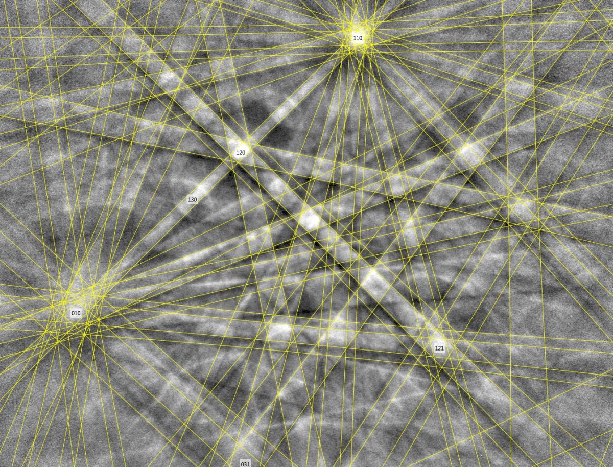
The phase identification process identified the phase as hexagonal AlN and this structure (in yellow) fits perfectly to the EBSP.

Example phase identification using combined EDS and EBSD. A high temperature steel contains second phase particles, as visible in the secondary electron image. The software interface shows simultaneous EBSP and X-ray spectrum acquisition from the large, dark particle visible in the SE image.
Most commercial EBSD systems are fully integrated with EDS. This enables the collection of chemical data at the same time as performing routine EBSD mapping: at each point in a map, during acquisition of the EBSD pattern, the X-rays are detected by the EDS detector and the full X-ray spectrum for that position is stored. The latest generation large area silicon drift EDS detectors (such as the Oxford Instruments UltimMax detectors) can collect 100’s k counts per second (cps) when analysing using standard EBSD beam currents (1-20 nA). Therefore, even at the fastest EBSD analysis rates up to 5000 patterns per second, the system can collect ~100 X-rays at each analysis point. This is sufficient to plot high quality element maps, plus the X-rays from multiple pixels can be combined to provide good quality spectra during subsequent offline analysis.
Given that there is little to no time penalty for performing simultaneous EDS measurements during EBSD mapping, it makes sense for it to be standard procedure to always combine the 2 techniques. The additional information provided from the EDS measurements enables verification of EBSD phase discrimination, highlights potential chemical variations that may otherwise have been missed or can explain why certain regions of an EBSD map were not indexed well. One such example is illustrated below, taken from a deformed igneous rock. The deformation map in the mineral plagioclase (using the grain relative orientation deviation map component) highlights some narrow bands of deformation and recrystallisation cutting across the largest grain. The corresponding Na EDS map shows that these deformation zones correlate with enriched Na content, likely due to late-stage fluid infiltration and alteration along microfractures. This interpretation would not have been possible without the additional information provided by simultaneous EDS.

EBSD phase map.

EBSD deformation map for the plagioclase (anorthite) phase, using a grain relative orientation deviation (GROD) component.

Na element map from EDS.
In some samples 2 or more phases are so crystallographically similar that EBSD alone cannot separate them. This phenomenon is seen in both material science and geological applications, and can cause problems for interpretations of the microstructure. There are a number of ways to resolve this issue, including detailed analysis of Kikuchi band widths, or post-acquisition reclassification of the phases using data processing software: these are examined in more detail here. However, in many cases the most effective way to separate the phases is using the chemical information from EDS.
Different commercial systems approach this in subtly different ways, but the basic principle is that, if the EBSD indexing process cannot distinguish between 2 phases, then the chemical information from simultaneous EDS results is used. This process can take place during the initial analysis or may be employed post acquisition as part of a reprocessing routine. The example shown in to the right, from a hard wearing tool steel, shows how the use of chemistry-assisted indexing enables correct discrimination between NbC and austenite (Fe-FCC), which are both Space Group 225 but with about 20% difference in the unit cell dimensions.
The use of chemical data to assist EBSD indexing can be limited by the poorer spatial resolution of the EDS technique. At beam energies of 20 keV, the X-ray source volume is typically 1-2 mm, approximately 1 order of magnitude greater than the effective resolution of the EBSD technique. Therefore, for analyses with very small step sizes, the use of the EDS signal to assist EBSD indexing can cause misidentification along phase boundaries and should therefore be applied with care.

Example application of chemistry-assisted indexing on a hard-wearing tool steel. Standard EBSD indexing (left centre) mis-identifies Fe-FCC and NbC for certain orientations (left centre, circled regions). The use of the chemistry during EBSD indexing (as shown by the EDS Nb element map) enables correct phase discrimination, as shown in the right-hand map. Sample courtesy of Wen Hao Han, The University of Sydney.
© Oxford Instruments 2026